
How do an EV charger and an electric vehicle achieve high-speed “communication” as soon as the charging connector is plugged in? This diagram provides a clear overview of the PLC carrier communication logic between European-standard EVs and charging stations.
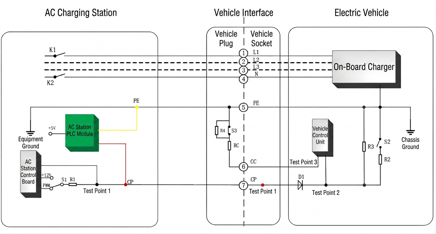
The entire system consists of three main components.
1. AC Charging Station (EVSE)
The charging controller serves as the main control unit, while the PLC Communication Module (HomePlug Green PHY) provides the high-speed data communication channel.
Through a coupling circuit, the PLC module superimposes high-frequency digital signals onto the Control Pilot (CP) line.
K1 and K2 are the main circuit contactors. When ISO 15118 communication is used, the contactors close only after the required communication procedures, parameter negotiation, and safety checks have been completed, ensuring safe AC power delivery.
2. European Type 2 Charging Connector Pin Configuration
-
- L1/L2/L3 and N: Three-phase or single-phase AC power supply.
-
- PE (Protective Earth): Provides protective grounding.
-
- PP (Proximity Pilot): Uses a resistance circuit to identify the charging cable’s maximum current capacity and can also help detect connector insertion.
-
- CP (Control Pilot): Performs two essential functions.
Basic Layer: 1 kHz PWM Signal.
The basic CP signal detects vehicle connection status and communicates the available charging current. Connector insertion is primarily detected through changes in CP voltage levels.
Advanced Layer: High-Frequency PLC Communication
High-frequency PLC signals are superimposed onto the CP line to support ISO 15118 communication, enabling advanced features such as Plug & Charge (PnC), Vehicle-to-Grid (V2G), secure authentication, and charging session management.
Key Differences Between Chinese GB/T and European Type 2 Connectors
-
- Chinese GB/T AC Connector: Uses the CC (Connection Confirmation) circuit for connector detection.
-
- European Type 2 Connector: Does not have a separate CC pin. Instead, the PP circuit identifies cable current capacity, while the CP line handles basic connection signaling and, when supported, PLC communication.
3. Electric Vehicle (Onboard System)
The On-Board Charger (OBC) converts AC power from the charging station into DC power suitable for charging the vehicle’s battery.
The onboard PLC communication module extracts and demodulates high-frequency PLC signals from the CP line.
Through the ISO 15118 communication interface, the vehicle and charging station exchange information such as:
-
- Vehicle authentication and identification
-
- Battery State of Charge (SOC), where supported
-
- Charging parameters and power requirements
-
- Charging session information
The R2/R3 resistors and diode D1 shown in the diagram form part of the standard CP detection circuit, allowing the vehicle to communicate its connection and charging readiness status to the charging station.
Complete European Type 2 PLC Communication Process
- Connector InsertionWhen the Type 2 connector is plugged in, the CP voltage changes, allowing the charging station to detect the vehicle connection. Meanwhile, the PP circuit identifies the charging cable’s rated current through its resistance value.
- Basic CP HandshakeThe charging station provides the CP signaling required by IEC 61851, including a 1 kHz PWM signal when appropriate, to establish basic communication with the vehicle.
- PLC Communication EstablishmentThe PLC module couples high-frequency OFDM signals onto the CP line. The vehicle and charging station then perform Signal Level Attenuation Characterization (SLAC) to establish their PLC association, followed by the necessary procedures to establish the ISO 15118 communication session.
- Data Exchange and Parameter NegotiationThe vehicle and charging station exchange information for authentication, charging parameter negotiation, and charging session management.
- Charging InitializationOnce communication, authentication, and the required safety checks are successfully completed, the charging station closes its main contactors (K1 and K2) when the applicable control conditions are satisfied, enabling AC power delivery.
Key Takeaways
Standard European AC charging can operate using basic IEC 61851 PWM signaling without requiring PLC communication.
HomePlug Green PHY PLC provides an additional high-speed communication channel by utilizing the existing CP line, eliminating the need for additional dedicated data wiring.
This advanced communication technology enables capabilities such as Plug & Charge, secure authentication, and supported bidirectional charging functions under ISO 15118.
It also forms the communication foundation for European CCS DC fast charging.
Technical note: PLC communication is not mandatory for every Type 2 AC charging session. Moreover, actual V2G functionality depends on vehicle hardware, charger capabilities, supported ISO 15118 versions, and applicable charging system requirements.
